Quantcast
Channel: DIY Audio Electronics from Zynsonix.com
Viewing all 105 articles
Browse latest View live

Attack of the Miniature Amplifiers!

$
0
0
Two exciting project completions to report today. Click on the links to read the full posts.

The JDS Labs CMoyBB, which is a miniature PCB based CMoy amplifier with bass boost.


...and the Miu Audio RA-1, which I believe is a design based on Grado's famous RA-1 headphone amplifier.


The Fine Print:
Please remember that building circuits and performing circuit modifications can be dangerous to you and/or your surroundings and should only be performed by a certified technician. The owner of this blog and all associated parties can not / will not be held responsible if you attempt a build or modification posted above and cause physical harm to yourself or your surroundings. Many electronics contain high voltages that can kill, and mods, if performed improperly, can be a fire hazard. Please keep this in mind. 


Recabling a Pair of Beyerdynamic DT880 Headphones

$
0
0
Beyerdynamic is a family-owned audio equipment manufacturer based in Germany that produces headphones, microphones and wireless audio systems. The headphones produced by Beyer are very solidly made, I'd imagine the rugged designs have the travelling DJ in mind. Still, the sound produced by Beyerdynamics top-tier headphones is something the discerning audiophile can really appreciate. The DT770, DT880 and DT990 models are ideal choices for the listener on a budget, and if one likes what they hear, there are pricier Tesla-based models that Beyer has recently introduced, namely the T-1, T-5p, and T-70.

The Beyer DT770, DT880 and DT990
The differences between the 770, 880 and 990 are surprisingly not subtle. The DT880 tends to be the most chosen for neutral listening, it is a semi-open design and has the most well-balanced presentation of the three headphones. The DT770 and DT990 are much more bassy, with the heaviest bass response coming from the closed DT770. The fully-open DT990 seems to have slightly less bass and a wider soundstage than the 770. I personally think that the 770 is the ideal movie and gaming headphone, the 880 is the best for analytical listening, and the 990 is good for audio enthusiasts who need a fun-to-listen-to headphone that matches a typical speaker system's bass response. 

While the sound of each headphone varies, the process of recabling them is nearly identical. Aside from the driver and cup design, the headphones appear to be identical inside and out. For this post, I will be recabling the Beyerdynamic DT880 headphones. Below is a stock DT880.

The Beyerdynamic DT880 Headphone

The wire for recabling a Beyer and still keeping the single-entry look takes a little bit more care than a typical headphone cable. When braiding, the wire should go from a litz braid to two twisted pairs about 2 and a half feet from the end. One of these pairs is nearly trimmed off, only leaving enough wire to get to the driver within the cup. The other twisted pair will be run through the headband. 

The braided Beyerdynamic cable
The wire is then sleeved and the long twisted pair gets some heatshrink to distinguish each side. 

Sleeved Cable

Then a four pin Neutrik connector is attached for balanced operation. If you are interested in reading more about 4 pin balanced connectors, please check out my post creating a 4 pin to TRS adapter cable

Cable terminated with a Neutrik 4 Pin XLR

Now that the cable is ready, the first step to getting inside the headphones is to remove the velour pads. These pads stretch over the frame of the cup, so there are no screws to remove, etc. You will notice a number of perforations on the inside of the pads, these holes make a big difference in the sound, covering them adds unwanted reverberation. If one replaces the velour pads with leather, it is preferable (in my humble opinion) to get the leather pads with the perforations inside. 

DT880 pads removed from the cups

The next piece is removed using a typical envelope opener to pry the plastic ring out of the cups. The plastic ring retains the driver and driver surround. Once it has been removed, one has access to the driver terminals. 

DT880 driver and driver terminals

There is generally a marking on the driver to determine the positive side. In this case it is a yellowish gold mark. I take the time to use a multimeter and verify this is the case before snipping off the stock wires. The left driver has three terminals, the center is the right signal which is not electrically connected to the driver but the wire that runs across the headband is connected to this terminal. The ground is also run from the ground of the left driver to the right driver. This is all removed and ignored as dedicated wires will be run directly to the drivers in the recable. This will remove unnecessary solder joints in the signal path and isolate the ground for balanced operation. Below is a photo of the shell of the DT880 stripped and ready for the recable. 

Beyer DT880 Shell

The latest models of the 770, 880 and 990 have a square opening that the stock wire is fed into, This square hole needs to be dremelled out so that it is round, then heatshrink built up on the new cable for a perfect fit. A custom retaining system is set in place to keep the cable from being tugged out of the cup. 

Wires soldered to the DT880 driver

The wire is soldered to the driver terminals with the assistance of engineer helping hands. The wire is then fed through the little grommet to the other cup. The headband is now placed over the wire and sealed back up using the zip-lock bag type mechanism. 

The wire is fed through the little grommets in the cups
The second driver is soldered on the same way, and we have a complete headphone!

Completed headphone

This headphone also has a balanced to single ended adapter so it can be used with both types of amps. 

Another angle

Thanks very much for taking the time to read this post. If you'd like to have a pair of Beyerdynamic headphones recabled (or any other headphones), please take the time to message Zynsonix


The Fine Print:
The above steps detailing the recabling of a headphone are for entertainment purposes only, and not to be performed under any circumstances. The owner of this blog and all associated parties can not / will not be held responsible if you attempt the process posted and cause physical harm to yourself, your surroundings or your property. Please keep this in mind.


Recabling the Phiaton MS 400 Headphones

$
0
0
There are just some things out there that men inherently love: power tools, fast cars, beautiful women, and carbon fiber. Carbon fiber is one of the most desirable looking materials on the planet, with it's crossweave of woven carbon nanotubes that can be used to build a Formula 1 race car, aerospace technology, or... a headphone.

The BMW Hommage clad in carbon panels

Yes the use of light weight, ultra-strong carbon fiber doesn't really serve some sort of utilitarian purpose on a headphone, but it sure looks awesome. Headphones have become of a bit of a fashion statement in the past few years, with Beats by Dre, House of Marley, Skullcandy and more recently Prada. Nowadays you get to pay for a name, fancy looks, and maybe if you're lucky, more than a couple of bucks went toward making it sound good. One can really only tell on a case-by-case basis and reading the reviews. But I digress; that's a tangent I'd rather not tackle at the moment.

Prada Headphones

Phiaton is a company that seems to straddle the line between style and good sound, making use of exotic materials like leather, burnished aluminum and, wait for it... carbon fiber! They surfaced only a few years ago  (2008) in the headphone arena and offer nearly a dozen product options, many of which are designed for portable use. Perhaps this is so people can see your good taste as you strut by.

As all headphones that eventually make their way into my clutches, these would be taken apart and recabled. The Phiaton MS 400 is here for this purpose. Stock, the headphones sound pretty decent for the price. The overall sound is warm and full. Bass could stand to go lower and be a bit more controlled, and the highs are slightly rolled off. This may sound negative, but overall I'd say the headphone has very good sound quality compared to other closed portable headphones. We'll see if a recable can help at all.

The stock Phiaton MS 400 headphone

Initially, 23.5 gauge red and black Cardas internally litzed copper in Teflon is braided into a four foot cable.

Braided Cardas copper wire

Next, the wire is sleeved with 1/8" black nylon multifilament and terminated with a ViaBlue mini connector. If you'd like to know more about the connector and see the inside, check out my post on a custom mini to RCA with ViaBlue connectors.

Sleeved and prepped cable

Now, the headphone will be opened to accept the new cable. The pads slide off vertically, exposing four screws on each cup.

Headphones with pads removed

Once the driver baffles are unscrewed, they can be removed exposing the solder terminals.

Phiaton headphone interior

The plastic on the inside of the headphone is fairly flimsy and light and will bend to the touch. Some mass will be added using some Dynamat Xtreme. The foam behind the driver is removed and used as a template to cut out the Dynamat, this is placed directly on the bottom, then a strip is run around the driver cavity. 

Mass damping using Dynamat Xtreme

The foam is then placed above the Dynamat is the same place it was initially. 

Foam returned to driver cavity

At this point, the new cable is soldered to the drivers, a small zip tie added for strain relief, and the headphone sealed back up. All done!

Recabled MS 400 Headphone

Thanks very much for taking the time to read this post. If you'd like to have a pair of Phiaton headphones recabled (or any other headphones), shoot us a message Zynsonix

If you're still craving more carbon fiber, check out Carbon Fiber Gear. There's plenty of great articles and if you need to shave a few seconds off of your bathroom breaks, there's a carbon fiber toilet seat available for purchase.


The Fine Print:
The above steps detailing the recabling of a headphone are for entertainment purposes only, and not to be performed under any circumstances. The owner of this blog and all associated parties can not / will not be held responsible if you attempt the process posted and cause physical harm to yourself, your surroundings or your property. Please keep this in mind.


The Objective2 (O2) Headphone Amp

$
0
0
People feel so strongly about audio reproduction that it often becomes akin to religion and politics and arguments ensue. Some listeners feel that a perfectly flat response curve and fully diminished THD levels (total harmonic distortion) are the holy grail, while there are others that enjoy the warm distortion and harmonics achieved with old triode technology and a frequency response that tapers the upper and lower extremes. Both are right in their own way, the former looking for perfect accuracy, the latter looking for a relaxing listening experience, and there are probably many listeners that fall in between.

The Objective2 headphone amp falls into the first category, where good measurements are the paramount objective. NwAvGuy has gone to great lengths to provide what many headphone listeners have been pining for, a low-cost headphone amp that achieves great measurements in a vast number of categories. While I don't fall into the category of pursuing perfect measurements (just look at all the number of tubes used in the builds on this site), I highly respect the effort that went into this build and all subsequent documentation.

Something that's quite impressive is that NwAvGuy does not make a penny from these designs. The PCB files are open source and circulated freely; users are encouraged to arrange group-buys on forums such as DIYAudio.com in order to procure the board and/or the front panel. Also, as of this writing, JDSLabs is offering both the O2 board and a unique front panel (to see the JDSLabs CMoyBB being built, please see my previous post). The total cost of the build is very reasonable and should fall under $100 including the case, custom front panel and wall-wart. Add a couple hours of soldering time and you'll have yourself an amp.

The Objective2 Sept 2011 PCB board

What's especially important with closely populated boards is starting with the small parts (resistors and diodes) and working your way up to the larger items such as capacitors and MOSFETs. If one doesn't follow this basic principal, it's much more difficult to fit your fingers into the small recesses between the larger items on the board.

Partially populated, all resistors and small parts in place

The battery clips may look crooked, but they were lined up carefully before soldering to ensure a perfect for for a 9V. This is something one doesn't want to try and adjust later as desoldering them can be difficult. The faceplate shown was procured from a DIYAudio group buy. Many thanks to MrSlim and FlynHawaiian for their efforts.

Fully populated board with faceplate

Faceplate from the DIYAudio group buy

There are a number of testing procedures on NwAvGuy's site to ensure the amp is working properly before you plug a pair of headphones in to ensure that you don't inadvertently damage them with high DC output.

A pair of Tenergy 9V rechargables were dropped in and secured with double sided tape and the unit was boxed up with the case specified by the bill of materials, a Box Enclosures B2-080. Gold was chosen as it's a bit more flashy than a plain black box. Screws were replaced with brass counterparts and the knob was a generic aluminum one from the parts bin, possibly made by Kilo.

Assembled Objective 2 amp

Once the amp had a few minutes to burn in, some cans were plugged in for a listen. All online reviews of this amp were avoided so the initial listening could be done without any pre-conceived notions. The amp reminds me quite a bit of the headphone output of the Benchmark DAC from a HeadFi meet. It's very crisp, clear and has strong, effortless bass. The bass may even be a bit better than the Benchmark was, if memory serves correctly. Both amps are quite analytical; I wouldn't choose them for my own personal musical enjoyment as my ears are sensitive and need the treble and upper-midrange to be a bit rolled off or fatigue sets in too quickly. One can see this amp being highly recommended for audio mastering work as it should convey every detail possible to the editor.

Immediately after building the amp, the input and output jacks were shorting with a variety of different plugs. It appears I received a bad batch as I didn't see any other documentation online regarding issues with the Kycon jacks. Rather than replace them with the identical items, Switchcraft jacks will be wired in as they are very trustworthy. The opamps will also be switched to the low-power versions made by Texas Instruments, which hopefully will be a little bit warmer.

More to come...


The Fine Print:
Please remember that building circuits and performing circuit modifications can be dangerous to you and/or your surroundings and should only be performed by a certified technician. The owner of this blog and all associated parties can not / will not be held responsible if you attempt a build or modification posted above and cause physical harm to yourself or your surroundings. Many electronics contain high voltages that can kill, and mods, if performed improperly, can be a fire hazard. Please keep this in mind. 


The ECP Audio / Beezar Torpedo Headphone Amplifier

$
0
0
It's been a long time coming; Dsavitsk started looking for builders for his prototype of the Torpedo, a CCS loaded, transformer coupled parafeed headphone amplifier back in March of 2010. The Torpedo is a simplified and more affordable version of the ECP Audio L'espressivo spud headphone amplifier and works with 6J6 tubes and equivalents, including the 5964 and 5844. The shortkit was just recently made available in December 2011 on Beezar after a number of DIY enthusiasts built the initial prototype and includes the chassis, custom transfomers from Edcor and the PCB. The remainder of the parts are listed in the bill of materials and can be purchased from the usual suspects (Mouser, Digikey, etc.). The total build cost, if not going crazy, should fall under $300.

The Torpedo Schematic from ECP Audio
The ECP Audio / Beezar Torpedo Shortkit

The most unique facet of the Torpedo is the length. At 14" deep, it's a very unique looking unit. The length was designed to keep the output transformers as far away from the power transformer as possible to minimize potential flux interaction. As anyone who's built a headphone amplifier with output transformers can tell you, this is a real concern; noise is very apparent when a sensitive driver is right next to your ears.

In the interest of a unique looking build, an antique copper / bright copper powdercoat color scheme was selected. Holes were drilled every inch in a line along the top left and top right for copper pop-rivets to embellish the chassis. The rear vent was cut out in favor of copper colored perforated metal above the power transformer. Also, holes were added to the bottom of the case for EAR isolation feet.

Fancy powdercoated Torpedo case (Bottom and Top)

The EAR feet were installed with a combination of a #6 screw and washer on the bottom and a lock washer and nut on top to ensure that they remain screwed in. 

Case bottom with EAR isolation feet

The initial population starts with the smaller parts, resistors, diodes, etc. This build won't deviate much from the bill of materials as the specified parts are of high quality, however the obligatory Kiwame carbon film resistors were dropped in. Since Kiwame / Koa Speers doesn't offer their resistors in 1M values, Takman carbon films were used in their stead. Also, the Neutrik 1/4" jack was substituted with the gold-plated version as their isn't much of a price difference.  

Initial population of the Torpedo Board

A matched pair of 4.7μF Clarity Cap ESAs were used as the parafeed caps. The ESAs are the same size as the SAs but with slightly nicer specs and tighter tolerances. The price was right at about $34 for the pair as of this writing and they're a perfect fit. The purpose of these caps is to block direct current (DC) from the output transformers.

Clarity Cap ESAs at 4.7uF

Almost fully populated

According to TomB and Dsavitsk, there is a small bit of audible noise when the top of the case is fitted on a completed Torpedo amp. Unfortunately at this point, builders have not been able to isolate the issue, despite trying things like grounding the heatsinks and adding grounded shielding to try to isolate the power transformer from the tubes. This build will be trying a slightly different approach; the tubes will be raised up out of the chassis using a custom fabricated metal panel that the tubes will mount to, hopefully protecting them from the power transformer noise. The PCB will be wired to a pair of chassis mount tube sockets which will sit on the metal panel raised by a set of nylon standoffs. The ideal measurement for the standoffs seems to be about 40mm, or a hair above 1.5 inches.

Below is the metal panel designed in Front Panel Express that Dsavitsk and I worked out. There are three holes to attach the nylon standoffs and two holes for the 7 pin tube sockets and the accompanying chassis mounts. This will necessitate two holes being drilled into the PCB to accommodate the left and right standoffs, which will be used to ensure a rigid mount so tubes can be swapped without the panel flexing.

Tube mounting panel designed in Front Panel Express

Below is the FPE fabricated panel in their nice bronze anodized color. 

Tube socket mounting board

Unfortunately, the panel was a little too wide at 39mm, so it was trimmed down a bit with a cutting disc. Also, underneath one of the screw holes are the traces on the PCB for the left and right channel inputs; we wouldn't want to knock those out, so a new screw hole was made a little closer to the tube socket on that side. Since the screws are so close to the top of the chassis, they were depth mounted to avoid any clearance issues. Finally, the ceramic tube sockets had to be sanded ever-so-slightly to fit in the holes. 

Tube sockets mounted

Now came the time to wire up the tube socket board. Because some of the pins are interconnected on the PCB, they would be shorted on the socket to decrease the amount of wiring necessary (1+2) and (5+6). A hundred ohm resistor was used to connect pins 5+6 to the PCB. This was done at the advice of Dsavitsk. Also added was a twisted pair of wires coming from pins 3 and 4 (the heater section) that will be powering an LED-based pilot light. Kimber TCSS wiring was used, it's my preferred hook up wire in tube amps as it's  relatively thick (19ga) but easy to work with and has a Teflon coating. The pins of the socket were covered with heatshrink tubing to prevent shorting. 
Tube socket board wired up

Holes were drilled into the PCB (into the ground plane area) and the nylon standoffs were mounted. The wires were carefully trimmed to the right size and stripped at the end and tinned (covered with solder) so that the wire strands wouldn't stray when inserted into the PCB holes. The board was screwed to the nylon standoffs. Finally, the amp is fully populated.


Fully populated Torpedo amp


Wiring detail under the mounting board


When the cover is added, the sockets come right up to the top of unit, perfect for rolling tubes without having to unscrew anything. 


Sockets once the cover has been mounted


The amp assembly can now be completed. The pilot light with bayonet style LED was wired up, the front panel holes were tapped for 4-40 screws and screws installed, the grounding screw and standoffs secured,  and a Kilo aluminum knob installed on the Alps Blue Velvet potentiometer.

Completed Torpedo Amplifier

Completed Torpedo - Back

Completed Torpedo - Front


Initial testing was done with a pair of headphones with 32ohm impedance. There is a smidge of audible noise that sounds like it's from flux interaction, but it's barely audible and hardly worth mentioning. I'd definitely consider it a non-issue. The amp sounds excellent so far, I'll be doing some more critical listening soon.


The Fine Print:
Please remember that building circuits and performing circuit modifications can be dangerous to you and/or your surroundings and should only be performed by a certified technician. The owner of this blog and all associated parties can not / will not be held responsible if you attempt a build or modification posted above and cause physical harm to yourself or your surroundings. Many electronics contain high voltages that can kill, and mods, if performed improperly, can be a fire hazard. Please keep this in mind. 


Building Amplifiers - Tools of the Trade

$
0
0
A number of readers have asked what one might start with if they were planning on building amps and other audio electronics. After a number of builds you come to depend on certain tools to get the job done.  There are some that you can get by without and some that are pretty essential. The list might be overwhelming, but many of the tools listed are of low cost and there are likely already quite a few you already have. There are always varying degrees of quality in tools out there, sometimes you can get away with the online special, and there are other times when you'll actually want to spend a few extra bucks if you'll be using that tool repeatedly. Below are many that I've found to be worthwhile in electronics work.


SOLDER & SOLDERING ACCESSORIES

Solder Station
The most necessary tool on this list. There are solder wands out there, but if you're remotely serious about building electronics, step up to a solder station. A solder station will usually have a means of adjusting the temperature, which is essential for turning down when soldering sensitive semiconductors or turning up when soldering a large binding post. The Hakko 936 is a highly recommended station and can be found under $100. 

The Hakko 936 Solder Station


Solder
Solder needs to have a nice mix of flux and a low melting point to be easy to use. Kester 63/37 and Cardas Quadeutectic solder are both highly recommended solders; I've personally had good luck with both as well. Both contain lead, so proper precautions are necessary when handling either. Refer to http://toxnet.nlm.nih.gov/ for information on the safe handling of lead and other dangerous chemicals in solder. There are also a number of tin-free solders, however they require much more effort to get a good shiny joint in my experience.

Cardas Eutectic Solder


Solder Tip Cleaner
A tip cleaner is a nice easy way to clean the tip of the soldering iron between solder joints to get off any oxidation. The Hakko 599B is full of brass coils that remove the oxidation and prevent the iron from dropping in temperature like a damp sponge would.

The Hakko 599B Solder Tip Cleaner

Solder Reel Stand
Not really necessary but a nice-to-have that keeps your bench neat; this little stand holds a reel of solder and allows you to draw the solder smoothly.

Solder Reel Stand

Solder Sucker
Solder suckers are immensely useful and quite affordable at around $5. I've actually found the cheap ones work just as well as the more expensive models. These make use of a tip that can withstand heat, such as PTFE, and a spring-loaded suction tube. Putting the tip up to heated solder and pressing the button to release the spring can quickly remove it from a circuit board eyelet, connector or wire.

A Solder Sucker from Parts Express

Helping Hands
A great little device for electronics that will hold wires and connectors in place while you solder. Generally these are made of metal, include two clamps, one on each side, and have a weight at the bottom. Some models also include a magnifying glass. These are also quite affordable, you'd be hard pressed to find a set over $10.


A traditional set of helping hands


Toothbrush and Isopropyl Alcohol
After populating a circuit board, there is usually quite a bit of unsightly rosin flux that has dried around the solder joints. Only $2-3 is needed to procure a basic toothbrush and a small bottle of isopropyl alcohol which can help remedy this situation. Wetting the toothbrush with the alcohol and scrubbing away will help remove the flux from the board.

Basic toothbrush and isopropyl alcohol


SAFETY RELATED ITEMS


Fume Extractor
Since solder has lead in it, it's in one's best interest to not breath in the solder fumes. A fume extractor will help remove the fumes from the air. There are a number of models out there, some are not much more than glorified fans, some are able to be positioned on a pivoting rod, and some have deluxe filters. Prices range from a few dollars to well over $100 depending on the quality and complexity.

A typical solder fume extractor

Protective Glasses / Goggles
Probably another no-brainer, it's important to protect your eyes from random bits of molten-hot solder and airborne metal dust. I haven't found a set I'm in love with, but the Dewalt protective glasses seem to work fine.

Ear Protection
You're going through all this trouble for better sound, make sure you protect your ears so they'll be able to enjoy it. Simple isolating ear buds can help to some extent or larger ear cups from companies like Peltor, Browning or Trademark are worthwhile when you're going to be cutting through a lot of metal.


TOOLS


Rotary Tool
I'd consider this an absolute essential; the rotary tool in my workshop is constantly in use. It can be used with sanding bits to de-burr drill holes, enlarge existing holes, cutting new holes and trimming down screws with the metal cutting disc attachment. There's quite a variety of tools and attachments made by Dremel to add utility to this little device. Dremel, Black and Decker, Dewalt, Kawasaki and other brands offer rotary tools, many of which work with the Dremel attachments.

Dremel tool with cutting disc


Desk Vise
Much like the helping hands, a desk vise will hold things for you while you work. The desk vise is well suited for holding small pieces of aluminum or steel that need to be trimmed, circuit boards to be soldered to, screws to be shortened and other various items. Below is an example, the Panavise 381 with a suction base, but there are many other varieties to suit various purposes.

The venerable Panavise 381


Flat and Phillips Head Screwdrivers
Probably a no-brainer, but with nearly every chassis and socket you'll be needing to secure something with a screw and / or a nut. A precision set of screwdrivers is also recommended for adjusting miniature board-mounted potentiometers and using small size #4 hardware. 

A precision screwdriver set

Set of Pliers
A set of pliers goes a long way. Pliers can be used to hold small nuts in place while tightening screws, holding small items that your fingers might be too large and clumsy to hold, trimming small pieces of metal and a variety of other uses. Even a cheap set will be worth it's weight in gold around the shop. 

A generic set of miniature pliers


Adjustable Wrench
For larger nuts that need to be tightened, like with potentiometers, stepped attenuators, balance controls, and switches, an adjustable wrench is worthwhile so you can get the grip you need that won't slip like a set of pliers would. A socket wrench may also work but it would need to be fairly deep to accommodate the above. 

Adjustable locking wrench


Socket Wrench
A socket wrench is a wrench with interchangeable heads or sockets that allow it to turn various size bolts and nuts. Great for mounting RCA females with nuts on the outside like Cardas and mounting binding posts. The socket wrench will ratchet either to one side or the other depending on how it's set which facilitates the tightening process. 

Socket Wrench and Sockets

Tap & Die Set
Prepping a chassis to hold PCBs, tube sockets, transformers and other items requires drilling the necessary holes, then tapping the holes for the proper size screws. This involves inserting a tap in a "T" wrench which holds the tap steady while one turns the wrench, "tapping" the hole. One could likely get by with just size #4-40, #6-32 and #8-32 tap set to start with (along with the obligatory "T" wrench) they are the most common sizes in building. 

A set of taps


Miniature Wire Cutter
It's worth spending a few extra bucks on a good miniature wire cutter, it will be used constantly to trim down excess leads after soldering. It needs to feel good in the hands and be sharp so that excess force isn't necessary to trim the leads. I've had good results with Klein and Xcelite. 

An Xcelite miniature wire cutter


Wire Stripper
Just like the miniature wire cutter, spend a few extra bucks here. There are quite a few wires in a point-to-point amplifier, so there will be a lot of wire stripping. Klein Tools makes great wire strippers in my experience. Wire strippers come with a variety of gauges they will work with. Generally, 18-24 gauge are most typically found inside amplifiers. 

Klein wire stripper

Greenlee punches
Greenlee punches are quite expensive. but worthwhile if you'll be using them frequently. If one is building tube amps and fabricating their own chassis, having common sizes for ceramic and/or Teflon tube sockets is a nice-to-have. The Greenlee units are basically a draw stud that tightens the die and punch together when a ball bearing nut is turned on the top (see figure below). This requires a pilot hole to be drilled drilled in the center of where the hole should be on the chassis to accommodate the draw stud. There are special tools made by Greenlee to tighten the dies but a socket wrench can also be used on a budget. The holes come out perfectly accurate, which is their real appeal. 


Stepped Drill Bit
A stepped drill bit is handy for making holes for tube sockets and large switches and jacks if one does not have the proper sized Greenlee punch for the task, or doesn't want to pony up the cash for a Greenlee die (perfectly understandable). A stepped drill bit starts off small at the bottom and incrementally gets larger. It can be difficult to get perfect results like with a Greenlee punch but they can be very accurate if used with a drill press. 


Drill Press
A drill press is a pretty great tool to have for chassis building; they offer much more precision than a hand drill, and don't come with the fatigue associated with trying to drill dozens of holes with a heavy battery-powered hand drill. Once can purchase a bench drill press for about $200 from companies like Rockwell or Delta that are very adequate, just be sure to have the room for it. 

Delta DP300L Bench Drill Press

Heat Gun
A heat gun is useful for shrinking heatshrink tubing over wires. The heatshrink can act as a strain relief for a cable, to prevent shorting if there are two exposed wires near each other, to keep multiple wires together for organizational purposes, or to color code wires among other things. Certain heatguns allow for attachments that can help direct the heat around a cable.

A Milwaukee Heat Gun


Pop Rivet Gun
One of my personal favorites. A pop rivet gun can be used in place of a screw and nut when something needs to be secured but will never need to be removed. The pop rivet is placed in a drilled hole and the gun trigger is squeezed, expanding the tail and securing the rivet in place. Easy does it.


A pop-rivet gun

There are certainly many others, but listed above are the basics. Know one that I missed? Tell us in the comments section!


The Fine Print:
The owner of this blog does not have any personal or monetary relationship with any of the brands mentioned above. The tools and items listed above can be potentially dangerous and should only be handled by a professional. Please remember that building amplifiers and other electronics can be dangerous to you and/or your surroundings and should only be performed by a certified technician. The owner of this blog and all associated parties can not / will not be held responsible if you attempt a build using the tools or items above and cause physical harm to yourself or your surroundings. Please keep this in mind. 


Glassware Audio LV-Regulator Power Supply

$
0
0
Wallwarts... you know them as the little black plastic boxes that take up precious real-estate on your wall outlet or your surge protector. These little devices are generally mass produced overseas as a cheap method of converting your house's AC (alternating current) to usable DC (direct current) for whatever device they'll be powering. This process requires transformation, rectification and filtering in order to make the power worthwhile for your device. Transformation is the process of converting the voltage from 120v (in the U.S.) to whatever the device is calling for, whether it be 9V, 12V, etc. Rectification periodically reverses the direction of AC to convert it to DC, usually using diodes or vacuum tubes in some circumstances. Filtering is reducing the power ripple to produce stable power and reduce EMI (electromagnetic interference), often times making use of capacitors.

Not all power supplies are created equally. Many high-end electronics shrug off the little wallwarts and have a dedicated power supply built-in, or even in a separate chassis. Using higher quality transformers and better filtering circuits improves the quality of power entering your equipment, which will hopefully improve the listening experience if all goes according to plan. As many forum members agree, there are a number of devices that can benefit from a dedicated power supply, such as the Squeezebox, Cambridge Audio DACMagic, Wadia 170 and 171 iTransport and the Musical Fidelity X-Series and V-Series components. 

This brings us to the Glassware LV-Regulator (LV standing for Low Voltage) which can be configured for 5v, 9v or 12v DC output and makes use of a 3A low-dropout regulator (LD1085). As stated by John Broskie on the Glassware website: "The LV-Regulator uses a simple RC filter (1 ohm & 10kµF) as a pre-filter before the LDO regulator and holds bypass capacitors for all the electrolytic capacitors and a 4.7µF/400V polypropylene shunting capacitor at the output. The 1-ohm resistor is a 4W device, so the maximum current output is 2A. The RC filter before the voltage regulator unburdens the regulator from having to deal with sharp transients."

The Glassware LV-Regulator board (copyright Glassware)

This board, when combined with a suitable transformer, will make a nice power supply for low voltage devices like many mentioned above. The one being assembled in this particular post will be 9v and making use of a center-tapped Hammond transformer. Below is the initial board assembly and the Hammond 166M10 3A transformer. Because the transformer is center tapped, the board would be configured as full-wave center-tapped. 

Transformer and LV-Regulator Board

Aside from the transformer and board, a few other things will be necessary, including a chassis, IEC inlet, power outlet, umbilical power cable, pilot light, and on-off switch. The IEC inlet will be a EMI/RFI filtering type that should help further clean up the power. For the power outlet, a Neutrik Powercon connector will be used. For the chassis, I'll be using a custom 8" x 5.5" chassis from Keith (Ebay member po1019). Below is a quick initial chassis layout for the build.  

Custom 8" x 5.5" chassis with mahogany panels

Initial chassis layout

Below is a photo of the chassis after the holes were drilled and it was powdercoated a cream color. I have a nice Greenlee punch for handling the Neutrik Powercon connector (it handles the Powercon, the locking 1/4" jack and other similarly shaped panel mounted jacks). The IEC inlet has to be cut with a Dremel cutting disc which requires a bit more time and effort. I typically drill four holes in the corners, then cut between them with the cutting disc, then finally use a hand file to smooth out the cuts. All the other holes on the chassis were created with a drill press. 

The LV Regulator Chassis

Next comes the process of adding the parts and the populated circuit board to the chassis. Thankfully everything fit without issue. 

Parts added to chassis

With everything in place, the circuit could be wired up. 16 gauge silver-plated copper in PTFE was used for all wiring, aside from the pilot light which was 18 gauge. The wood side panels were then slipped in place and screwed in. 

The LV Regulator all wired up

With the wiring complete inside the unit, there will be a need to get the amps to the transport it will be powering via a cable. The cable from a power supply to the unit it is powering is typically called a "umbilical" cable. The center of this cable is a twisted pair of 18 gauge silver plated wire, one for power and one for return. This was carefully wired to a small 3 pin power connector that closely matches the Wadia 171i input. Multiple layers of heatshrink were used to ensure to possibility of a short within the plug. 

Creating an umbilical cable for the power supply

I decided to shield this cable, so some additional steps are necessary. The twisted pair was covered with Teflon tape, then a bus wire wrapped around it. This bus wire will conduct to the foil shield that will be wrapped around it. 


The foil tape is made by 3M and is a basic way to reduce EMI (electro magnetic interference). I used it rather than copper mesh to keep the cable from getting too bulky. 

3M foil tape wrap

The cable then gets another layer of teflon tape on top.


More to come...

The Fine Print:
Please remember that building circuits and performing circuit modifications can be dangerous to you and/or your surroundings and should only be performed by a certified technician. The owner of this blog and all associated parties can not / will not be held responsible if you attempt a build or modification posted above and cause physical harm to yourself or your surroundings. Many electronics contain high voltages that can kill, and mods, if performed improperly, can be a fire hazard. Please keep this in mind. 


DIYTube Get*Set*Go Single Ended Amplifier

$
0
0
Shannon Parks, head-honcho of DIYTube, has made plenty of projects available since 2003 when the DIYTube ST35 clone was made available. Since then, a handful of projects have been released, from the 60 watt Eiclone amplifier to driver boards for Dynacos to stand-alone single-ended amplifiers like the Clementine and Get Set Go. The projects are all well documented, feature circuit boards for easy building and if a builder runs into trouble, DIYTube features a forum with a very friendly user-base that is happy to help with problems.

This post is dedicated to the building of the Get*Set*Go. Get "Set" Go is a cute play on words for SET (Single Ended Triode). The tube compliment features an on-board 6SL7 driver and 6AX5GT rectifier, which feed two 6B4G power tubes running in single-ended Class A with no feedback. Power output is approximately 3 watts, so it's important to pair this amplifier with some very efficient speakers.

Get Set Go Schematic from DIYTube

Get Set Go Power Schematic from DIYTube

A variety of transformers can be used, including James, Triode Electronics, Edcor, etc. James 6113HS outputs were the initial recommendation on the BoM (bill of materials), however it seems there are no local suppliers at them moment, and having them shipped overseas is an expensive proposition due to the weight. Transcendar TT-312-OT 5K were settled on for the outputs for this build, they're a very highly recommended value and made in the U.S.

A pair of  Transcendar 312-OT output transformers

The power transformer is the Triode Electronics PA-774, which is a well-made clone of the Dynaco ST-35 PA-774 transformer. The laminations of this transformer are a natural metal finish, and since the 312-OT outputs are wrapped with adhesive black cloth tape, I wanted the PA-774 to match a little better. The particular cloth tape that Gery at Transcendar uses runs $50+ a roll, which wouldn't really be worth the cost for a single application, so black engine enamel was settled on to darken the lams on the PA-774 for its high heat properties.

Black Engine Enamel used to darken transformer laminations

Also from Triode Electronics is a pair of reproduction C-354 chokes. These little guys will help reduce ripple in the power supply. The chokes arrived with a bit of excess transformer lacquer that had solidified roughly on the edges, which is perfectly fine but not the most attractive thing to look at. A little bit of sanding and a black oil-based Sharpie touch-up worked wonders.

Triode Electronics C-354 Chokes

I had the aluminum chassis made for this build from my friend Keith (po1019 on Ebay) with beautiful walnut side panels.

Custom chassis with walnut side panels

The build begins with the silk-screened bright red PCB made of FR4 fiberglass. Beginning with the smallest parts (resistors and diodes) and working up to the larger parts (capacitors), the board is carefully populated.  This begins with Kiwame carbon film resistors, along with Vishay and Mills wirewound power resistors.

Board with Kiwame, Mills and Vishay resistors in place

Some fun boutique parts that will be dropped in are a set of four Nichicon Fine Gold and two Elna Cerafine electrolytics. Generally the "audiophile" marketed electrolytics (think Black Gate, Elna Silmic / Cerafine, Nichicon Muse / Fine Gold) are much larger than their similarly rated counterparts, but in some rare cases, they'll fit on a circuit board without issue. Also to be included are a set of matched Jupiter Beeswax HT 0.22uF caps. Below you'll note the populated board with above items. Also, the power supply electrolytics (Panasonic 150uF 450V) are being bypassed with a pair of Solen 1.0uF 630V film caps. This is probably not necessary as the two chokes should minimize the power ripple, but they were sitting in the parts bin and it couldn't hurt ;)

Bottom of the populated Get*Set*Go Board

Top of the populated Get*Set*Go Board

Next came creating all the necessary holes in the chassis using a combination of the drill press, Greenlee die punches for the tube holes and a Dremel cutting disc for the IEC inlet. Below is the chassis ready for a fresh coat of paint at the powdercoater.

Chassis top plate with all necessary holes
Chassis bottom plate with ventilation holes

The chassis was then powdercoated a warm cream color.

Powdercoated GSG Chassis

The components can now be added. Cardas copper binding posts, Cardas RCAs, Teflon 8-pin tube sockets, and VT4C aluminum tube surrounds were installed. The chokes and transformers were installed using a combination of rubber washers, brass washers, locking washers and brass nuts. The rubber washers are used to help dampen vibration from the transformers to the chassis. A heavy duty toggle switch was added to the front of the chassis for the sake of convenience. The usual vintage-style pilot light was also added to the front panel.

Initial parts installation

Once the parts were in place, the PCB could be fitted on top of the standoffs. This is when you find out how accurate your drill-work is ;) Thankfully all the holes lined up and a few screws were placed to keep the board secured.  

The GSG PCB in place

The Get Set Go makes use of convenient barrier terminal blocks so that the board can easily be removed without an iron if the situation calls for it. Each wire is trimmed to size and a small binding post is attached at the wire termination, the binding post is then screwed to the board with a standard Philips head screwdriver. 

Most of the wiring up complete

I did take note of Shannon's suggestion that a few of the power resistors should be mounted on the other side of the board to maximize heat dissipation, so R15B, R16B, R19 and R20 were relocated. Two pieces of shielded Cardas 2x21.5 were trimmed to size and used to run the low level signal to the board. Finally the Bayonet light featuring a 6.3V LED was wired to the board, completing the project. The bottom was screwed on and some nice tubes were dropped in place.

The Get Set Go from the front

I was able to source a nice pair of matched Raytheon 6B4G tubes, a coin-base GE 6SL7 driver and a Sylvania 6AX5GT.


The Get Set Go from the rear

I designed the nice little engraved plate in Illustrator. Anyone who wants to use it is welcome (for non-commercial applications).


The amplifier started up right away with no issues thanks to Shannon's great online documentation. The response was crisp and clear, and the bottom-end was more plentiful than I was expecting from such a low wattage output. I'd imagine with the 5K output transformers the output is likely around 2.5 watts. It still needs a little help from a subwoofer in my humble opinion, but the sound is quite nice.

Want more? Read about another DIYTube SET build: the Clementine.

The Fine Print:
Please remember that building circuits and performing circuit modifications can be dangerous to you and/or your surroundings and should only be performed by a certified technician. The owner of this blog and all associated parties can not / will not be held responsible if you attempt a build or modification posted above and cause physical harm to yourself or your surroundings. Many electronics contain high voltages that can kill, and mods, if performed improperly, can be a fire hazard. Please keep this in mind. 


Balancing the AKG K702 Headphone

$
0
0
The AKG K702 headphone is quite simply a black AKG K701 heaphone with a removable mini 3 pin cable. It's very nice to be able to remove the cable from a headphone with the click of a button, which is where the 3 pin mini-XLR comes into play. Switchcraft is well known for these connectors and offers them in a number of different pin configurations. Clicking the little black button on these connectors allows them to disconnect from the jack, so if a user runs over their cable with the wheel of a chair, desires a shorter or longer cable, or wants a cable of higher quality, it's very easy to swap a new cable in. Zynsonix offers replacement cables for the K702 among other headphones with removable cables if one is in the market.

With the existing 3 pin connector in the AKG K702, the two grounds for each channel are commonly connected. This won't work for a balanced connection to a balanced headphone amplifier where the grounds are run separately, so the existing three pin connector will be removed in favor of a 4 pin mini-XLR from Switchcraft.

In this post, a pair of K702s will be getting repaired with some high quality Eys 99.999% pure silver wiring (5Ns) in PTFE tubing. This particular pair of K702s had the previous jack accidentally ripped out (perhaps the headbanging got a bit too frenetic ;) ), but luckily everything inside is still in good working order. (I've found that with other AKGs, getting the existing jack out can be quite tricky, requiring a Dremel tool and quite a bit of patience). One will notice in the photo below, the white wire is the ground, in which both the left and right ground are commonly connected. In order to get inside the plastic shell, the grill needs to be rotated using a pair of jewelers screwdrivers, then two small screws are removed from underneath the grill.

AKG K702 opened

The first task would be to wire up the Switchcraft 4-pin mini XLR jack with silver wire, this would be replacing the existing wire within the headphone. Each piece was made a little longer than necessary and color coded for easy reference with electrical tape. The solder joints were covered with very small diameter heatshrink tubing to prevent the Teflon tubing from moving while the jack was being installed.

Silver wire soldered to Switchcraft mini 4 Pin jack

Now the jack could be slipped inside of the existing plastic shell. No dremeling or filing necessary is necessary when using a genuine Switchcraft jack. A strong adhesive does need to be used to keep the jack in place however. 

Switchcraft jack installed in the plastic shell

The stock wiring was removed at this point, a desoldering pump used to get off excess solder, and the new wires soldered in place. The solder points for the left driver are at the left-most and right-most points, and the solder points for the right driver travel along the headphone band, which are both closer to the center. Silver wiring was wired to the to the terminals and the plastic shell and grill were reinstalled. 

The plastic shell being reinstalled on the K702s

At this point, the matching silver cable could be built. Starting with a 4 pin mini XLR plug, the silver wires were soldered in place and small diameter heatshrink tubing was placed over the joints to prevent slippage of the Teflon tubing.  

4 Pin Mini XLR plug with wires soldered in place

The metal jack barrel was then slipped in place over the plastic piece housing the contacts. 

Metal barrel covering plastic housing

The wires were then braided in a litz formation and the strain relief clamped down on the wire tubing to prevent movement. 

Silver wire braided and strain relief clamped

The cable was then sleeved with soft black nylon multifilament. The remaining piece of the jack was filed to allow for the large diameter cable, then slipped over the sleeving and screwed to the metal barrel. A piece of adhesive black heatsrhink was added to act as an additional strain relief and help to keep the sleeving in place. 

4 Pin mini XLR completely installed

Cable sans mini connector

A Switchcraft mini connector could now be installed. You can see more details on a mini connector being installed in this previous post: Silver Plated Copper Mini to RCA Cable. The cable could now be clicked into place on the now repaired AKG K702. The mini connector is inherently non-balanced, but the user can now easily upgrade to a balanced cable when they are ready.

Completed cable on the AKG K702 headphones

UPDATE (6/14/12): The Quincy Jones Q702s are nearly identical, although the internal jack proved to be much more difficult to remove. The Q702s below were recabled using Zynsonix Ecs ultra pure ohno cast copper in Teflon.

Rewired with Zynsonix Ecs wire

These AKGs feature a fully balanced cable. 

Quincy Jones Q701 Balanced

I hope you found this post entertaining. Please be sure to contact Zynsonix if you have a pair of AKG K702 or Q701s that need rewiring, or any headphone for that matter.


The Fine Print:
The above steps detailing the repair and recabling of a headphone are for entertainment purposes only and not to be performed under any circumstances. The owner of this blog and all associated parties can not / will not be held responsible if you attempt the process posted and cause physical harm to yourself, your surroundings or your property. Please keep this in mind.


DIYTube 6L6 Clementine Single Ended Tube Amp

$
0
0
Shannon Parks, owner of DIYTube, has made a number of projects available since 2003 when the DIYTube ST35 clone was made available. DIYTube is both Shannon's small business located in central Illinois and a close-knit forum featuring a handful of helpful and prolific members. Projects on DIYTube include the 60 watt Eiclone amplifier to driver boards for Dynacos to stand-alone single-ended amplifiers like the Clementine and Get Set Go. The projects are all well documented and feature circuit boards for easy building.

The Clementine can be configured to use with 1626 Darling tubes (hence the cute name... oh my darling Clementine) to output 3/4 of a watt or with 6L6 tubes (equivalents: 6L6GC / 807 / 1625 / 6BG6) for a fruitful yield of 5 watts (see what I did there?). This post is dedicated to the building of the 6L6 Clementine.

DIYTube Clementine Schematic

The transformers used for this build aren't quite as fancy as the Transcendars found in the Get*Set*Go build, these would be the tried and true Edcor XPWR005-120 power and GXSE15-8-5K outputs. If you aren't familiar with Edcor, they're likely one of the best-value transformer manufacturers in the U.S. They've been around since 1971 and have been offering distinctive "True Blue" transformers to hobbyists for decades. All of their transformers are made-to-order, so there's usually a 4-6 week waiting period before you get your order, which really isn't so bad considering their pricing.

Edcor power and output transformers

Deviations to the BoM (bill of materials) include the typical Kiwame / Koa Speers carbon film resistors, along with a pair of matched Mundorf Supreme 0.22uF capacitors. Barely squeezed in was a pair of 100uF 100V Elna Silmic IIs. Also packed in was a little bit more capacitance in the power section using 150uF caps and a pair of 2.2uF Solen film bypass caps. Lots of green and red on this board, looks like Christmas time ;)

Top of the populated Clementine board

Important to note is the 8 pin sockets need to be carefully lined up before and during soldering. It's possible to end up with them at a slight angle, which will cause the tubes to jut out at an angle on the top of the chassis. With a bit of heating the joints and shifting, I was able to get them nice and parallel with the board. Once everything was placed, a nice scrub-down with a toothbrush and rubbing alcohol was in order to get all the rosin flux off the board.

Bottom of the populated Clementine board

For the chassis, Keith (po1019 on Ebay) fabricated me a very nice one made from aluminum and walnut side panels. Keith's work is very professional and I hope to continue using his chassis for my future endeavors.

Custom chassis with walnut side panels

One of the more time consuming parts of a build is creating all the necessary holes in the chassis using a combination of the drill press, Greenlee die punches for the tube holes and a Dremel cutting disc for the IEC inlet. Below is the chassis ready to head over to the powdercoater.

Prepped chassis top plate

Chassis bottom plate with vent holes

The chassis was then powdercoated a nice cream color. 

Powdercoated Clementine Chassis

...and the transformer bells a dark red. The transformers also got some brand new nylon screw insulators and brass hardware. I'm not sure why, but often times the nylon insulators that come with transformers are worn looking and discolored. This process is a decent amount of work. The original hardware has to be removed, the bells sanded and taken to the powdercoater, the nylon insulators squeezed into place, then the brass screws trimmed down to fit, then the acorn nuts tightened in place, all for the sake of presentation.
A beautified Edcor transformer

The next task is to add some rubber grommets to the chassis where the wire from the transformers runs inside. This is to protect the wire from rubbing up against a potentially sharp edge on the hole and shorting to the chassis metal. It's an added precaution for the sake of safety. 

Rubber grommets on the chassis holes

The next process was to add the switch, pilot light, power inlet, signal input RCAs and output binding posts. The RCAs are Cardas GRFA, the binding posts are Cardas Economy ACBP, which are still on the pricey side in my humble opinion but not as much as the CCBP copper posts I typically use. Nearly all these items are installed with a socket wrench.

Chassis-mount items in place

The PCB and choke were then installed. The PCB was installed using standoffs, screws and lockwashers to prevent anything from coming loose down the line. The choke was installed using rubber washers underneath to damp any vibrations from making their way to the chassis, along with size #6 hardware.

Chassis and PCB in place

Next the Edcor transformers can be installed. Only two were added at this point as one of the bells was a little shy on the paint from the powdercoater and it needed a respray. The transformers also get rubber washers underneath, along with size #8 hardware, including lock washer, washer, nut and screw.

Two of the Edcor transformers in place

The Edcors were wired into place. I've seen a number of members double up the 6.3V taps in order to use other tubes, but for this particular build I only plan on using 6L6s so I won't be performing that mod. The extra 6.3V tap (brown) will be dedicated to the pilot light. The power wiring and front switch was also wired up during this step. Directly after the fuse is a GE Thermistor wired on solder tabs (the little black circle in the middle of the photo below). A thermistor is a resistor which has a resistance that varies depending on temperature. In this case, the NTC thermistor is used for inrush-current limiting. A higher resistance is provided initially which prevents large currents right after turning the amp on. Once it has heated up, the resistance is much lower, allowing higher current flow. 

Transformers and power wired up

More to come!

The Fine Print:
Please remember that building circuits and performing circuit modifications can be dangerous to you and/or your surroundings and should only be performed by a certified technician. The owner of this blog and all associated parties can not / will not be held responsible if you attempt a build or modification posted above and cause physical harm to yourself or your surroundings. Many electronics contain high voltages that can kill, and mods, if performed improperly, can be a fire hazard. Please keep this in mind. 


Building a Balanced Microphone Cable

$
0
0
Pro Audio and Home HiFi are two very different markets. The brands are different, the purposes are different; the pro's main concerns lie with good measurements and durability while the home listener is more likely to pursue tweaks and boutique audio parts to reach a sound they find pleasing. Today I'll be crossing the lines and assembling a microphone cable using some fancy Cardas internally litzed copper in Teflon.

In many years of experimenting with different wire types, I've settled with Cardas wire in many applications because of it's perceived warmth. Warmth is an audiophile term that means a slightly rolled off treble, not really in the pursuit of accuracy but more pleasing sounding music. My ears tend to be sensitive and a little bit more warmth goes a long way, it can help me listen longer before fatigue sets in, and can warm up the treble on a headphone that would otherwise be difficult to listen to. This may be attributable to the individually enameled strands, so when there are many strands of differing gauges all isolated from one another, the slight difference between the signal in all these strands over the length of the cable causes a slight smearing effect which the human ear may perceive as warmth. Just a hypothesis on my part, but it seems logical. In the case of using Cardas copper with a microphone, it will hopefully assist in increasing the warmth of the voice.

Cardas offers its internally litzed copper in Teflon hook-up wire in a variety of gauges (9.5, 11.5, 15.5, 17.5, 20.5, 23.5 and 33). The thicker 9.5 and 11.5 gauges are more ideally suited for speaker cable and power cords, the 15.5 and 17.5 gauge could be used for internal hook up wire in amplifiers, the thinner 20.5 and 23.5 are both great for interconnects and headphone cables, and the 33 gauge's purpose is for tonearm wire. Selected for this particular build is three strands of the 20.5 gauge wire, along with gold plated Neutrik XLR connectors (NC3FXX-B and NC3MXX-B).

Cardas copper wire and Neutrik gold plated XLRs

As mentioned above, the copper is enameled, so once the wire is stripped, either very hot solder needs to be held over the conductors to remove the enamel, or the conductors need to be dipped in a solder pot. This needs to be done before the wire is soldered to the connectors. Once three of the wires are soldered to the NC3FXX-B, the wire is tightly braided and secured with a piece of electrical tape.

Braided Cardas wire

In the interest of protecting the delicate signals of the microphone, this cable will feature a floating shield to help block EMI / RFI interference. Copper mesh sleeving is run over the length of the cable and connected at the ground shell of the NC3FXX-B.

Copper mesh shielding

The wire is then wrapped with PTFE tape as an additional dielectric and to help keep the mesh shielding from bulging in certain areas when the nylon sleeving is slipped over it later on. PTFE (or Teflon) tape is common plumbers tape and can be found at the hardware store.

Cable wrapped with PTFE tape

The final layer is the soft black nylon multifilament sleeving. The purpose of this layer is for looks, and can help reduce microphonics if the cable brushes against anything during recording.

Cable sleeved in soft nylon multifilament

Finally, the remainder of the NC3FXX-B can be installed, the strain relief placed over the sleeving and the soldered connections, the metal barrel slipped over top of the assembly and the boot is inserted on the other end of the cable, slid up to the metal barrel and screwed in place. The other connector is installed on the other side (boot slid on first, connections soldered, strain relief placed and metal barrel slid on top, then the boot screwed in place).

Completed XLR microphone cable

The cable is now complete and ready to do some recording work. If you need a custom microphone cable made for you, be sure to contact Zynsonix.com.


The Fine Print:
The above steps detailing the building of a cable are for entertainment purposes only and not to be performed under any circumstances. The owner of this blog and all associated parties can not / will not be held responsible if you attempt the process posted and cause physical harm to yourself, your surroundings or your property. Please keep this in mind.


Custom RCA Switch Box for Audio

$
0
0
So in any given audio setup there may be multiple amplifiers (e.g. a headphone amp, speaker amp, etc.) or possibly multiple sources (e.g. a record player, CD player, DAC from a computer, etc.). A switch box keeps it simple so one doesn't have to reach in the back of the rack and manually switch interconnects to listen to particular equipment. They will commonly have multiple RCA jacks (or in some cases XLR jacks) for both input and output and a switch which is commonly 2 pole (stereo with common ground) or 4 pole (stereo with isolated grounds).

They may be handy, but not all switch boxes are created equally; audio enthusiast know that using a generic one can potentially degrade the audio quality, a situation which just isn't worth the added convenience. All the ingredients need to be of high quality to ensure there is no notable degradation of the signal.

This post will be detailing a simple 6-to-1 switch box making use of high quality parts to ensure transparency. Parts include a Swiss-made Elma 04-1264 switch, EAR isolation feet, Philmore Teflon insulated gold plated RCAs, Neotech UP-OCC sold-core copper wire in Teflon and a lovely custom-made chassis from Keith (ebay seller po1019).

The first task was to take the chassis and drill holes for the switch, feet, and RCA connectors. It may be easy to use a ruler and mark where each hole is going to be, but drilling the holes perfectly in line *probably* won't happen, even on a drill press. When there are multiple items lined up, the eye can very easily identify any slight aberrations to a straight line. I was able to get them pretty close in this case. The chassis was then powder-coated a nice cream color.

Chassis prepped for the build process

The next process is installing the RCAs. Because the powdercoat insulates the aluminum, the back of the holes were filed so the RCAs would ground to the chassis so the chassis would act as a shield. You might be gawking at the Philmore RCA blister pack and thinking "wow, that looks like dollar store garbage"... Looks can be deceiving; under the homely packaging are a pair of very nice quality gold RCAs with Teflon insulation. I like to use Cardas RCAs in many of my builds, but when one is using seven pair, like in this case, that would be quite costly; that's where the Philmores come into play. Each one is cranked on using a socket wrench and the ground washer bent at 90 degrees. 

The chassis populated with Philmore RCAs

Each of the ground washers is then tweaked together with a pair of pliers and a ground wire is run through them, then soldered in place. This particular wire is silver but any bus wire would be fine. This ensures that there is a common ground between all inputs and outputs. 

Ground wire connected to each RCA

Now comes the fun part; wiring up each RCA to the Elma switch. Seeing which solder lug corresponds to each switch position is relatively straight forward, simply look through the transparent plastic at the location of the gold contacts. Each wire is soldered in place and a small amount of heatshrink is placed over the connection. 

Beginning the wiring process

The Neotech wire was kept nice and short for each connection. On the bottom, EAR isolation feet were fitted with a screw, lock washer and nut.

Wiring complete

The box could now be assembled and the nicely finished wood panels placed on the sides. Below are a few photos of the finished product.

Switchbox complete!

Switchbox Front

Switchbox Rear

Switchbox Bottom

Some nice points about this design are the short signal paths thanks to the small chassis, the Teflon insulated wire and RCAs, the gold contacts on the switch and the point to point wiring with no circuit board for the signal to run through. This box could either be used to allow 6 inputs and 1 output, or 1 input and 6 outputs. With a larger box and a second switch, there could be both multiple inputs *and* outputs. Or there could be two of these boxes daisy-chained, allowing for 6 inputs and 6 outputs. Tons of options!

Update: I created a nice little logo "iO" standing for input output and had it custom engraved on a brass plate for the top panel. Looks rather sharp I think :) Some additional photographs with the plate are below.


The Fine Print:
The above steps detailing the building of a switch box are for entertainment purposes only and not to be performed under any circumstances. The owner of this blog and all associated parties can not / will not be held responsible if you attempt the process posted and cause physical harm to yourself, your surroundings or your property. Please keep this in mind.


MC Step-Up Transformer using Altec 4722

$
0
0
Despite the extreme convenience of computer-based audio systems, the turntable has not lost it's place in the hearts of many audiophiles. Sometimes that extra effort can be worth it, balancing the plinth, brushing the dust off the record, cleaning the stylus, flipping the record after a few songs, the list goes on. There's just something nice about that analog warmth of that teeny tiny stylus wandering through the grooves of a well pressed record.

One of the requirements for owning a turntable is a phono pre-amp. A phono pre-amp brings the low-level signal from the record player up to a point where it can be run to a standard amplifier. Equipment like CD players and DACs don't have this requirement because their output is already at a suitable level. So, a very small gauge wire runs from the cartridge through the tone arm and goes to whatever jacks are on the turntable, generally RCAs on more modern decks. A pair of RCAs are run from these jacks to the phono pre-amp, which amplifies the signal and passes it on to the main pre-amp or integrated amp in the users system. Occasionally, the pre-amp or integrated amp will have a built in phono input, but many enthusiasts prefer a separate unit as the quality can be better. To complicate matters further, many phono pre-amps only amplify the signal of a moving magnet (MM) cartridge. There are also moving coil (MC) cartridges that have an even lower signal that the phono pre-amp simply does not have enough gain to play at a proper listening level. In order to remedy this, one can use an MC step up transformer.
A common step-up transformer, the Ortofon ST-80 SE

An MC step up transformer is completely passive, no electricity is needed to run it. The signal runs from the turntable to the MC step up transformer which amplifies the signal a small amount, then the signal runs to the phono preamp, which amplifies it further to the point where it can be run to the main-pre amp or integrated amp, where it is amplified yet again before it makes it's way to the speakers. So the flow would be Record Player > MC Step Up > Phono Pre > Pre / Integrated.

Many DIYers have taken to the fact that vintage microphone transformers can be used as an MC step-up device. As JELabs has stated: "Moving Coil cartridges behave very much like condenser microphones - low impedance and low output - requiring a voltage boost. Step-up transformers are passive devices and as long as they are wired properly, they are virtually noiseless. To me a wide bandwidth input transformer is the most elegant way of boosting MC output to MM phono level." There are a variety of units that fit the bill, from the Altec 4722 and 15095, Denon AU320, RCA MI12399A, Tamura TKS83, and Thordarson T-43606-A just to name a few. Below you will see a variety of these units in step-up devices made by JELabs.

A Variety of Step Up transformers

I'll be making use of the Altec Peerless 4722, it's one of the most popular vintage units and commands a price because of that demand, but from the way JELabs described it, it seemed that the units have a bit more of a euphoric warmth than the others, which I always appreciate. The Altecs are in the shape of a vacuum tube with eight pins at the bottom designed to fit into a vacuum tube socket. The chassis was custom-made by Keith, eBay seller po1019, and is a very fetching little unit. Holes were drilled for the RCAs, ground posts and switches and punched for the tube sockets that would be holding the Altecs.

Prepped Chassis
Cardas RCAs (GRFA) and ground posts (GRND) will be adorning the petite chassis. These were secured using a small socket wrench.

Some Cardas bling
More to come...


The Fine Print:
The above steps detailing the building of a MC step-up transformer are for entertainment purposes only and not to be performed under any circumstances. The owner of this blog and all associated parties can not / will not be held responsible if you attempt the process posted and cause physical harm to yourself, your surroundings or your property. Please keep this in mind.


Decware Zen Head ZKIT3 Portable Headphone Amp

$
0
0
The competitive portable headphone amplifier market can be a difficult one to approach. Manufactures quickly churn out new designs and form factors so quickly that unless you spend lots of time on HeadFi, it's difficult to keep track of them all. Between Ray Samuels, HeadAmp, HeadRoom, iBasso, Fiio, and many others, there are enough offerings to make your head spin.

The company Decware, known mostly for their non-portable, tube-based amplifiers, released a portable headphone amplifier back in 2008. While it was only four years ago, there have been hundreds, if not thousands, of portable amplifiers released since then that may have made some headphone enthusiasts forget about it. It was reviewed favorably many moons ago by HeadFi member Skylab whose opinion I respect, and Decware is offering the PCBs and chassis on his website, so I figured it would be a nice diversion to put one together and have a listen, even if it is a few years old ;)

The Decware Zen Head PCB

One of the nice things about the Zen Head PCB is that there's no SMD soldering to worry about, which is almost a given with more modern portable designs. Just regular old through-hole components here. This may not be the best beginners project as there isn't really any online documentation other than a bill of materials to populate the board. Also unusually, the parts values are printed directly on the board rather than part designations.

Rather than simply ordering the BoM, I opted to try a few other parts. All the resistors are Takman REX carbon film, and there are quite a few of them as seen below.

Takman carbon film resistors - pretty in pink

The capacitors were switched with Nichicon / Wima equivalents. Also added were a pair of gold sockets so the OPA2132P op-amps could possibly be rolled in the future. All other parts remained identical to the BoM except for items that were out of stock and necessitated a substitute. After the population of all the parts the board is quite colorful!

The populated PCB

The chassis is a little long compared to other portable amps as the battery doesn't fit on or over the board, but in a plastic battery holder in the back. Compared to something like Ray Samuel's Shadow, this amp is massive, but it will still fit in your pocket or transport just fine in a case. A pattern was drilled on the top of the case for heat dissipation, although it's doubtful that much will be generated.

Zen Head in PCB in case

I noted that the PCB was a little long and ran into the battery compartment. Since there's no traces at the end of the board, the PCB was sanded down a bit so everything would fit nicely. The battery strap was then soldered in place.

Attachment of the battery strap
Next the front plate needed to be drilled. A template was printed from the Decware site that was printed at actual size (not fit to page, very important!) and taped to the front of the plate. The plate was then drilled using a drill press and the holes de-burred.

Drilled front plate

More to come!

The Fine Print:
Please remember that building circuits and performing circuit modifications can be dangerous to you and/or your surroundings and should only be performed by a certified technician. The owner of this blog and all associated parties can not / will not be held responsible if you attempt a build or modification posted above and cause physical harm to yourself or your surroundings. Many electronics contain high voltages that can kill, and mods, if performed improperly, can be a fire hazard. Please keep this in mind. 

DIYTube Get Set Go 300B Headphone Amp

$
0
0
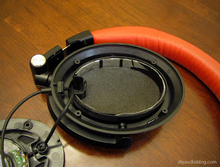
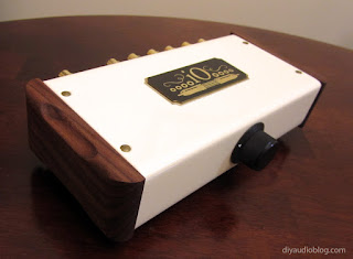
It's been a little while since the last post, and there's a good reason for that; I've been gathering parts for a very special DIYTube Get Set Go made specifically for the Audeze LCD-2 headphones. The Get Set Go is a single-ended triode design made first-and-foremost for high-sensitivity speakers that only need a few watts to fill a room with sound, such as the Planet 10 Audio Frugel Horn. I did have the fortune to build the Get Set Go for speakers previously and was impressed with the overall tonal character and quality of the sound.
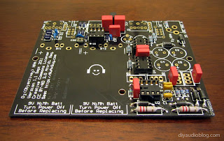
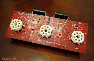
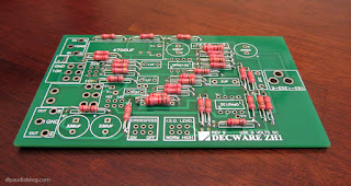
The Get Set Go Board from DIYTube

You may be wondering why someone would be using a speaker amp for a pair of headphones. A typical headphone amplifier will output relatively a small amount of power compared to the speaker amplifiers (in small fractions of a watt measured in milliwatts). The Audeze, as well as certain other planar magnetic headphones like the HiFiMan, really benefit from some added wattage to sound their best as they aren't the most sensitive drivers. Hense, using a low-powered speaker amplifier makes sense, but there are some changes that are necessary.

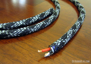
The biggest change is the output impedance. While speakers are typically 4, 8 or 16 ohm, headphones often range between 32 and 600 ohm. The Audeze headphones that the amplifier is being made for are 50 ohm (although I have also seen them listed as 60 ohm). Since 50 ohm single-ended output transformers don't really exist on the market, you can either have one custom wound, or try and find something that would have an equivalent turn ratio. There's a handy calculator that Shannon of DIYTube recommended that will give the equivalent turn ratio for this purpose. A 3.5K / 50 ohm output transformer would have a turns ratio of 0.12, or 8.367:1. Gery at Transcendar offers a 1.6K / 16 ohm single-ended transformer, the TT-023-OT, which is a 10:1 ratio and close enough for our purposes. Per Shannon, The reflected load would be a touch more linear and lost max output would be minimal.

Secondly, learned from previous experiences like with the Millet Jonokuchi, and to a much lesser extent, the 
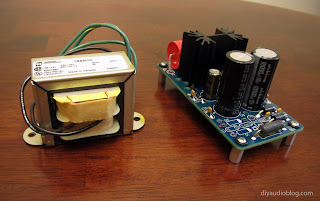
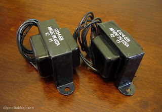
ECP Audio Torpedo, headphone amplifiers do not like their output transformers to be close to the power transformer. When they are too close in proximity, there is something called flux interaction when the magnetic waves interfere with one-another and cause an audible hum with certain headphones. So not only will the output transformers be moved to the opposite side of the chassis, but rather than using an EI transformer for power, a toroid will be used instead as they create much less of a magnetic field. Antec is one of the few manufacturers out there that builds certain toroids specifically for tube amplifiers. The Antec AS-2T300 would be a good substitute for the PA774 with a bit higher ratings.

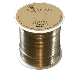
So other than the transformer choices and their position, this build will be fairly similar to the previous Get Set Go. To make things a little different, 300B tubes will be used rather than 6B4Gs. Also Mundorf Silver Oil capacitors will be taking the place of the Jupiter wax paper caps. The Mundorfs should be a little more detailed, which the Audeze can benefit from with their warmer/darker presentation.

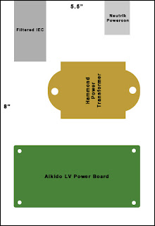
The first action-item on the list was the chassis. I always like to create a virtual mock-up of the chassis layout to see different set-ups and settle on what I feel will work the best. Note that in this layout, the output transformers are distanced from the power toroid and chokes.

Virtual Chassis Layout

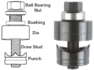
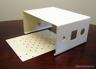
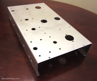
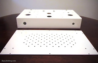
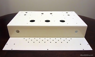
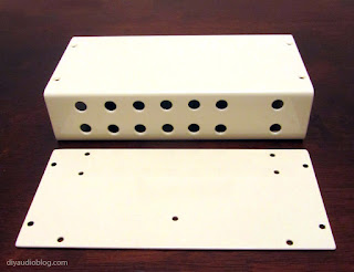
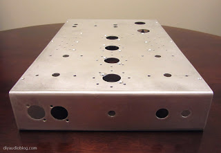
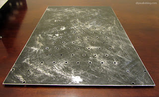
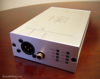
Once this is settled, I forwarded the dimensions over to Keith (ebay seller po1019) to fabricate the chassis. The virtual layout is then used as a guide to lay out the parts, take measurements and make markings, and ultimately start drilling / cutting away. After prepping a number of aluminum and steel chassis, I have a small collection of very handy Greenlee punches, which are ideal for making clean holes for tubes and sockets. The metal area (which will be behind the little red tab on the Neutrik locking plug) to release the headphone plug was recessed a bit by sanding using a Dremel and by hand for adequate clearance.

The prepped aluminum chassis

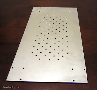
I decided that this chassis would have a more unique and artistic finish. Something more worn and rustic looking. I was actually inspired when I was scrapping off the dark grease on an old baking sheet. This finish starts with some black engine enamel that is then sanded and scrapped by hand minutes after spraying. It produces and interesting texture in my humble opinion.

Textured Bottom Plate

Texture Detail

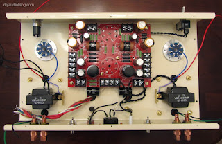
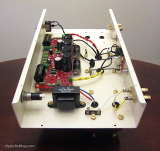
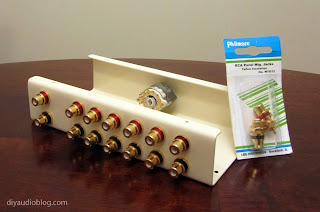
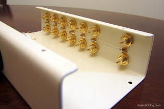
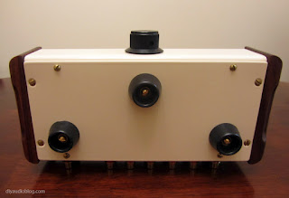
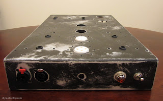
The texture is achieved by hand using worn out sandpaper at different times of paint dryness, along with the sharp point of a scissor to get the longer lines. Once the texture was where I wanted it, I gave the chassis two coats of clear satin enamel. The parts can now be dropped in place. I began with the smaller pieces, including the headphone sockets, which were flush mounted and secured with black oxide screws. The switch, pilot light, RCAs, binding posts, IEC, Teflon 300B sockets and hole grommets were all installed next.
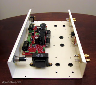
Part installation on the chassis

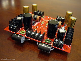
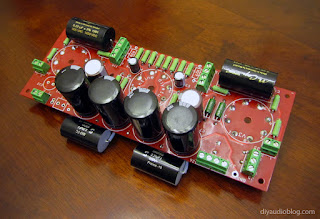
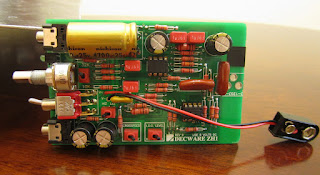
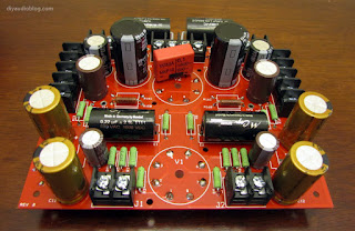
Next comes the fun part, the population of the PCB. Varying from the BoM, we have Elma Silmic II caps, Nichicon FineGold caps, Kiwame and Mills resistors and Mundorf Silver/Oil Caps. Slight changes to the circuit includes the Wima 0.1uF snubber cap and a pair of Solen 630V 5.6uF bypass caps in the power section.

The populated Get Set Go Board

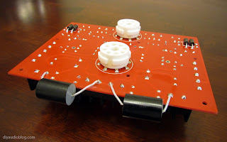
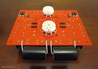
On the bottom of the board, at Shannon's suggestion, we have a few of the Mills power resistors to help distribute the heat a little better. 

Bottom of the board

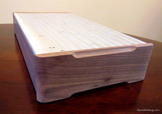
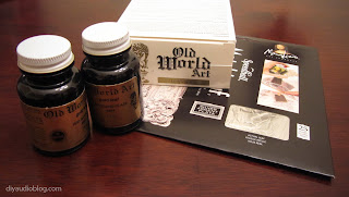
Now comes the long process of preparing the wood side panels. I decided on an antique silver leaf finish for these pieces. Since there is no off-the-shelf option for antique silver leaf that was readily available, I'm using some Speedball brand silver leaf pieces and some Old World Art brand leafing and antiquing materials.

Leafing Materials

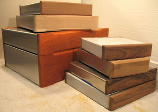
Below are the wood side panels for the chassis before any prep.

Wood Chassis Panels

The first step in the antique leafing process is a red basecoat. This is typically used with a gold foil, so we'll see how it performs with silver. Below is the wood with the basecoat applied.

Red antique basecoat

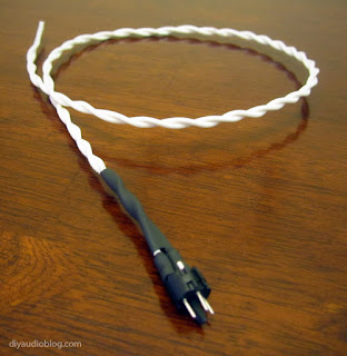
 After two basecoats and a layer of adhesive size, the wood is covered with the silver foil sheets. This is a very unusual process, the foil is incredibly thin and will tear apart if it catches your fingers, so you have to be delicate. each foil sheet is laid down with a little bit of overlap.

Silver foil sheets laid in place

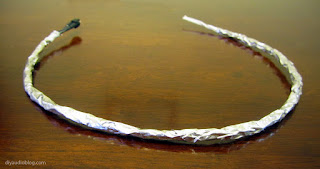
The foil is then burnished with a cheesecloth to have it form the curves of the wood. This is a messy process and the foil flakes will end up everywhere. They are so thin that you'll find them floating in the air. Once this is complete, a layer of sealant is used to protect the foil. 

Silver foil after burnishing

The antiquing kit included an antique glaze that is made for gold so it's a brownish hue. It didn't look right on the silver. Instead I chose to rub it down with powdered graphite before sealing it again. Then two layers of satin clearcoat were added for additional protection of the finish.

More to come

The Fine Print:
Please remember that building circuits and performing circuit modifications can be dangerous to you and/or your surroundings and should only be performed by a certified technician. The owner of this blog and all associated parties can not / will not be held responsible if you attempt a build or modification posted above and cause physical harm to yourself or your surroundings. Many electronics contain high voltages that can kill, and mods, if performed improperly, can be a fire hazard. Please keep this in mind. 


Pure Silver Mini to Mini Cable

$
0
0
A short mini to mini cable cable can be very handy when connecting a portable audio player to a portable amplifier. In some cases it's worthwhile to use a digital audio output, but not all portable devices offer this, so the venerable 3.5mm mini to mini will work perfectly well. In this particular post, I will be assembling a mini to mini cable using Cardas 5N (99.999% pure) silver wire and a pair of Neutrik mini connectors, the Neutrik NYS-231 BG to be exact. The B in the nomenclature stands for the black shell, and the G stands for gold contacts. This particular connector is chosen over the Switchcraft 35HD and the Canare F12 as the body is smaller and more easily fits on the face plate of portable amplifiers. You'll notice below that the connectors come in three parts, the connector piece with solder tabs, a barrel and a small tube that acts as a dielectric so the left and right solder joints do not short to the barrel, which is connected to ground.

A pair of Neutrik NYS-231BG

You may notice that the barrel inlets are rather small and not completely ideal for thicker sleeved cable. Because of this, I dremeled out the barrel inlet to create a larger opening. 

Barrels dremeled for larger diameter cable

Once this is complete, it is necessary to sand or file the rough areas so they don't grind up against the wire during use. Once the barrels are prepared, the solder tabs should be identified with a multimeter. In this case, the shorter leg A is the left signal (aka tip), the longer leg B is the right signal (aka ring), and C is ground (aka sleeve). 

Pinout of the Neutrik mini connector

As mentioned above, this cable will be using solid silver wire from Cardas. This wire will be sleeved with Teflon (PTFE) tubing. 

Cardas silver wire and Teflon tubing

Each wire is trimmed to the appropriate length and the Teflon tubing is then slipped over top. The Teflon acts as a dielectric and prevents the strands (aka conductors) from shorting to one another. It's a very good idea to get Teflon that's for a larger gauge than the wire you are using so it slips over it easily. In this case, 24 gauge silver is covered with 22 gauge Teflon.

Silver wire sleeved with Teflon

The three wires are braided together and soldered to the Neutrik connector. It's important for the Teflon tubing to go right up to the solder taps to prevent shorting.

Silver wire soldered to the Neutrik connector

Next comes the black nylon multifilament sleeving made by Techflex. This is 3/16" size, cut to length using a hot knife from Partsexpress. The hot knife prevents fraying at the ends by slightly melting where it cuts. Also note the dielectric material is slid in place before the barrel is screwed on. 

Black Nylon Multifilament

The barrel can then be screwed in place, and the other Neutrik connector installed the exact same way. In the photos below, 1/2" heat shrink is slipped over the barrels to provide additional strain relief and to offer the feel of a "rubberized"-type layer.  

Completed mini to mini cable


This can now be the connection between a portable audio player and a portable amp and not take up much real estate at all. Thanks for taking them time to read this post. If you are interested in purchasing a completed mini to mini cable, please contact Zynsonix.com.

For more pure silver goodness, check out a previous post detailing the build of pure silver interconnects

The Fine Print:
The above steps detailing the building of a cable are for entertainment purposes only and not to be performed under any circumstances. The owner of this blog and all associated parties can not / will not be held responsible if you attempt the process posted and cause physical harm to yourself, your surroundings or your property. Please keep this in mind.


Furez Copper Subwoofer Cable

$
0
0
A subwoofer only reproduces a limited range of audio in your system, most likely a frequency range within 20Hz and 100Hz. With this being said, subwoofer cables aren't as critical as the interconnects responsible for a much wider range (in my humble opinion). So, if you're weighing the benefits of subwoofer cable versus a pair of interconnects between your CD player and amp, I'd say go with the interconnects first. Still, as audio enthusiasts, we can't simply ignore our poor subwoofers, can we?

Today I will be assembling a pair of subwoofer cables from Furez FZ162AA audio cable. This is a reasonably priced cable that features thick 16 gauge oxygen-free copper conductors (99.997% pure, aka 4Ns), a very adequate foamed polyethylene dielectric and a dual-shield (tinned copper braid and a aluminum foil wrap) to help protect against EMI/RFI interference. I'll also be using some Furez FZ100BS black and grey sleeving to dress up the cable a bit, and a set of Cardas GRMO Rhodium over silver-plate RCAs.

The cable itself is nice and thick, thicker than the Cardas Crosslink 1i interconnect cable.

Furez FZ162AA Audio Cable

Taking a look a little closer, you'll notice the thick 16 gauge copper conductors. Normally audiophile interconnects are between 20 and 24 gauge, so this is a bit thicker than typical and thus will have additional capacitance (Capacitance @ 1KHz: 20.86 pF/ft). One could even use it for a speaker cable at this thickness. Whether or not this will be beneficial when used as a subwoofer cable remains to be seen.

Furez cable detail

As mentioned above, I'll be using some Furez FZ100BS black and grey sleeving to dress up the cable. This sleeving is made specifically for Furez products by ViaBlue. To see some of ViaBlue's bling, check out this mini to RCA cable made using their products. The FZ100BS is made from Monofilament Polyethylene Terepthalate (PET) and Fiber Fillers.

Furex FZ100BS black and grey sleeving

Do note that a hot knife is needed to cut the sleeving, otherwise it will fray, as you will see in the image above. The hot knife melts the sleeving together and prevents this. Also note that as you sleeve the cable, you will lose some length as the sleeving is expanding slightly. This amounted to several extra inches for each five foot cable length.

Noting the cable stripped below, you will see the two 16 gauge conductors, one in red dielectric, one in black. You will also see the mesh copper shield. For this particular cable, the mesh shield will be soldered to the ground on the source side and not connected on the other (floating shield configuration).

Stripped wire

Here is the opposite end of the cable after tinning the conductors. Tinning simply means covering the conductors with solder in this case. On this end of the cable, the shielding is not connected, so it is trimmed down and isolated with 3M electrical tape. Note that the black conductor (ground / return) is cut slightly shorter intentionally.

Tinned conductors

Now we will be soldering the Cardas RCA connector to the conductors. This is done by removing the barrel of the connector, then sliding it over top of the cable with the tinned ends and lining them up with the appropriate solder terminals. The red conductor (signal) goes to the center pin and the black conductor (ground / return) is soldered to the inner barrel. The Cardas GRMO requires quite a bit of heat to ensure a proper joint. I find that a solder station with adjustable temperature is necessary. The joints should be strong and shiny when complete. 

Cardas GRMO soldered in place

Once the soldering is complete, the RCA needs ample time to cool (they will be extremely hot to the touch). Then the outer barrel can be screwed in place and 1/2" adhesive heatshrink placed on top to act as a strain relief. 

Barrel and heatshrink added

I tend to like to cover about half of the Cardas barrel with the heatshrink so that some of that shiny gold bling is still visible on the completed cable.  

Heatshrink in place over barrel

All that's left is heating up the heatshrink with the heat gun and we have a completed cable. A second identical cable was made for the right channel and now we have a very fancy pair of subwoofer cables.

A complete set of subwoofer cables

Hope you enjoyed reading this post. If you are interested in having your own custom subwoofer cable (or any other cable) made, please contact Zynsonix for a quote.

The Fine Print:
The above steps detailing the building of a cable are for entertainment purposes only, and not to be performed under any circumstances. The owner of this blog and all associated parties can not / will not be held responsible if you attempt the process posted and cause physical harm to yourself, your surroundings or your property. Please keep this in mind.


Keith Michael Kirby

$
0
0
Very sad news, Keith Michael Kirby, the maker of very fine custom audio chassis, passed away on Tuesday, Dec. 25. Per the Albany Democratic Herald, Keith passed away peacefully at his home at the age of 50.

Keith Michael Kirby

Please view the Obituary.

Keith made it possible for many in the DIY community to build beautiful tube amps with his custom chassis.

Keith's beautiful custom chassis

Without Keith I would have never been able to complete my projects like this Dynaco mkIII monoblock amplifier below. He was always extremely friendly and he had a great passion for audio. It saddens me greatly that we won't be able to discuss our personal projects any longer. The DIY community simply won't be the same without his great contributions. May he rest in peace. 

My Dynaco mkIII featuring Keith's chassis


Contributions in memory of Keith may be made to SafeHaven Humane Society, P.O. Box 2018, Albany, OR 97321.

Balanced XLR to RCA Cable

$
0
0
Balanced XLR interconnects are what many people consider to be a superior connection between components. Typically found in Pro-audio equipment, they feature three wires rather than the two in an unbalanced RCA interconnect. The three wire system includes hot, neutral and ground. Current flows through the hot and neutral with both an inverted and non-inverted version of the signal. The component only needs to sense the difference between the two signals which assists in rejecting common noise. Common noise includes RF and ground loops, both of which can be quite annoying.

Some higher-end components have taken notice that balanced XLR interconnects can be more ideal and include them as optional inputs and/or outputs. Unfortunately there are many components that do not offer them, so you may end up with a component with XLR outputs and another with only RCA inputs. In this case, an XLR to RCA cable can be used.

The parts needed are relatively self explanatory. An XLR connector on one side (may be male or female depending on the component), an RCA plug on the other side, and three wires to connect them. One can also use only two wires and short the XLR internally between pins one and three. Note the diagram below that pins one and three are connected to the sleeve of the RCA and pin two is attached to the tip.


Starting with a Neutrik NC3-FXXB (3 pin female XLR connector), each of the pins are identified by the small number that's actually printed on the front of the plug.

The inside of a Neutrik NC3-FXXB

If you follow this blog, you've already seen countless litz braids of silver plated copper in PTFE, so we will skip that and move on to the soldering of the individual wires to the solder tabs on the Neutrik XLR connector. Each joint should be heated quickly but adequately (not too long which could melt the plastic casing) which will result in nice shiny joints.

Wire soldered to the Neutrik XLR

Next comes the sleeving. In this particular case, the braided wire is covered with soft black nylon multifilament. The black nylon multifilament is made by the company TechFlex and has a nice vintage look. It can be purchased from online retailers like Cable Organizer and WireCare. In order to sleeve the wire, a hot knife is used to cut the sleeve to prevent fraying, it is then slowly slipped over the braided wire and once completely covered, the other end is cut with the hot knife. To hold the sleeving in place, adhesive heatshrink is used on the ends where the strain relief from the plug will eventually cover the cable.

Sleeved cable

As you will note below, the strain relief system is placed over the heatshrink to give it something to "grip" to. The metal barrel is then slipped over the front of the XLR plug.

Barrel and Strain Relief

The boot can now be slipped over the other end of the cable and screwed in place to secure the barrel and strain relief system. Neutrik does offer the FXX line with a number of different colors. I'm using red here to denote the right channel. 

XLR side is complete

Moving on to the other side of the cable, the RCA connector will be attached to the cable. First, the metal barrel for the RCA is slipped onto the cable, then the RCA connector soldered in place. Both the number 1 connection and number 3 connection from the XLR side are soldered to the ground or "sleeve" in this particular configuration. The number 2 connection is soldered to the signal or "tip". Once soldered in place, a small piece of heatshrink (in this case red) is used to prevent shorting between the ground and signal. The nylon sleeving is then slipped as far forward as it can go and the strain relief on the sleeve is crimped around it.  

RCA connector soldered in place

Now another piece of adhesive heatshrink is placed over the bottom of the RCA connector to act as additional strain relief and further secure the sleeving.

Heatshrink sleeving in place

Now the metal barrel of the RCA can be screwed on. The cable is now complete and can be tested. 

A single completed cable

The pair of XLR to RCA cables

I hope you enjoyed this post. If you are interested in purchasing a completed XLR to RCA cable, please contact Zynsonix.com.

The Fine Print:
The above steps detailing the building of a cable are for entertainment purposes only and not to be performed under any circumstances. The owner of this blog and all associated parties can not / will not be held responsible if you attempt the process posted and cause physical harm to yourself, your surroundings or your property. Please keep this in mind.


AES EBU 110 Ohm Digital Cable

$
0
0

The very first real-time software MP3 player was a program called WinPlay3. This program was released way back in September of 1995, back in the days of half gig hard drives. As MP3s gained popularity and began to distract computer users from glorious MIDI music, Winamp from Nullsoft was released in 1997 and by the next year, Winamp in its various iterations was downloaded over 3 million times. Several years later, the first version of iTunes was released to the public in 2001. Fast forward to today, a little over a decade later, and computer audio has become very widely accepted and many audiophiles are more likely to fire up a PC than pop open a compact disc player.

The WinPlay3 Program

Because the CD player is going the way of the dodo (obsolescence), audiophiles choose to interface their PC with a DAC (digital audio converter) in order to extract the music in the best sounding way possible. A DAC requires a digital signal be carried from the PC to the external DAC. In some cases the PC has a direct output for a digital signal from the motherboard or sound card, in other cases, a user may choose to use a USB to SPDIF converter box, such as the M2tech HiFace or Musical Fidelity V-Link to name a few.

Digital signals can be carried a few different ways, either optically or via a coaxial cable. Many enthusiasts frown upon optical cables due to perceived jitter and myriad other issues, although I have found the glass ones to be acceptable in the past. Optical cables actually isolate the ground from one device to another which can be a benefit in the case of a dirty ground at the source. The other option, a coaxial cable with a single center conductor isolated with a dielectric and a return which is typically a copper mesh over the dielectric, can be terminated with either an RCA or BNC.  In the case of the AES/EBU, there is still the copper mesh over the dielectric and there are two conductors in the center.

Standard digital coaxial cables are preferred to be rated at 75 ohms, and since BNC connectors are legitimately 75 ohms, they are preferred, but in many cases BNC connectors are not offered and an RCA will suffice. If you are lucky and your PC output and DAC both have an AES/EBU jack, then you’ll have the best possible connection between your devices. AES/EBU coax cable should be rated at 110 ohms.
AES/EBU, also known as AES3, was developed by the Audio Engineering Society (AES) and the European Broadcasting Union (EBU) way before the first software MP3 player in 1985 (although revised in ’92 and ’03) and is effectively the professional version of S/PDIF. Much more additional information regarding the AES/EBU standard, including protocols, time slots and channel status bits can be found at http://en.wikiaudio.org/AES_EBU.

Musical Fidelity V-Link 192 featuring an AES EBU connection

Now that we covered what an AES/EBU is and where it came from, I’ll go ahead and assemble a nice audiophile quality one. One of the fortunate things about the AES/EBU protocol is that is calls for a standard XLR connector, of which there are many audiophile versions floating around, I’m sure some of which use time-corrected flux capacitors and pixie dust gathered during ancient times. I’ll personally be using the DHLabs Silver Sonic XLRs, which is a strange name as the contacts are gold-plated pure OFC copper (no brass!), but they’re great connectors for the dollar, and the DHLabs Silver Sonic D-110 110ohm coax cable, which has silver plated copper conductors within a PTFE dielectric, spacers for constant impedance and a 100% coverage shield.

Silver Sonic D-110 Cable and XLRs

First on the agenda is covering the wire with some nice sleeving. I selected the Techflex brand Carbon Reflex sleeving, which is a polyethylene terepthalate material braided with 3M Ultra reflective monofilament. In simple terms, the weave reflects light and looks pretty impressive.

As noted in the photo below, there are two insulated wires (positive and negative) and a drain wire which connects to the shield for the ground. Also in the center is the Silver Sonic XLR female pieces.

Sleeved with Carbon Reflex

...and here are the Silver Sonic XLR male pieces.

Silver Sonic XLR male connector

Although not necessary, I sleeved the drain wire with Teflon like the other two conductors for uniformity.

Drain wire with Teflon sleeve

These wires are soldered in place on each of the male and female connectors. The ground wire (the drain wire in this case) is soldered to pin 1, the positive wire (red in this case) is soldered to pin 2, and the negative wire (black in this case) is soldered to pin 3. Also note that with the Silver Sonic connectors, slipping the boot over the decorative sleeving requires some patience.

XLR Pin Diagram

Once everything is soldered in place, the barrels of  the DHlabs connectors are slid over the soldered connections and the three screws over each connector are replaced. The two screws over the boot in the back back a very substantial strain relief system. Below you will see the finished digital AES EBU cable. 

Finished digital AES EBU Cable


Hope you enjoyed reading this post. If you are interested in having your own custom digital AES EBU cable (or any other cable) made, please contact Zynsonix for a quote.


The Fine Print:
The above steps detailing the building of a cable are for entertainment purposes only, and not to be performed under any circumstances. The owner of this blog and all associated parties can not / will not be held responsible if you attempt the process posted and cause physical harm to yourself, your surroundings or your property. Please keep this in mind.


Viewing all 105 articles
Browse latest View live