So in any given audio setup there may be multiple amplifiers (e.g. a headphone amp, speaker amp, etc.) or possibly multiple sources (e.g. a record player, CD player, DAC from a computer, etc.). A switch box keeps it simple so one doesn't have to reach in the back of the rack and manually switch interconnects to listen to particular equipment. They will commonly have multiple RCA jacks (or in some cases XLR jacks) for both input and output and a switch which is commonly 2 pole (stereo with common ground) or 4 pole (stereo with isolated grounds).
They may be handy, but not all switch boxes are created equally; audio enthusiast know that using a generic one can potentially degrade the audio quality, a situation which just isn't worth the added convenience. All the ingredients need to be of high quality to ensure there is no notable degradation of the signal.
This post will be detailing a simple 6-to-1 switch box making use of high quality parts to ensure transparency. Parts include a Swiss-made Elma 04-1264 switch, EAR isolation feet, Philmore Teflon insulated gold plated RCAs, Neotech UP-OCC sold-core copper wire in Teflon and a lovely custom-made chassis from Keith (
ebay seller po1019).
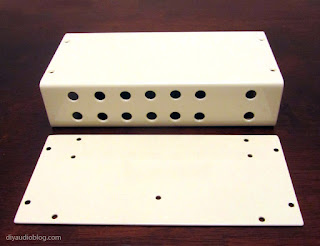
The first task was to take the chassis and drill holes for the switch, feet, and RCA connectors. It may be easy to use a ruler and mark where each hole is going to be, but drilling the holes perfectly in line *probably* won't happen, even on a drill press. When there are multiple items lined up, the eye can very easily identify any slight aberrations to a straight line. I was able to get them pretty close in this case. The chassis was then powder-coated a nice cream color.
![]() |
| Chassis prepped for the build process |
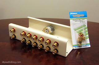
The next process is installing the RCAs. Because the powdercoat insulates the aluminum, the back of the holes were filed so the RCAs would ground to the chassis so the chassis would act as a shield. You might be gawking at the Philmore RCA blister pack and thinking "wow, that looks like dollar store garbage"... Looks can be deceiving; under the homely packaging are a pair of very nice quality gold RCAs with Teflon insulation. I like to use Cardas RCAs in many of my builds, but when one is using seven pair, like in this case, that would be quite costly; that's where the Philmores come into play. Each one is cranked on using a socket wrench and the ground washer bent at 90 degrees.
![]() |
| The chassis populated with Philmore RCAs |
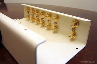
Each of the ground washers is then tweaked together with a pair of pliers and a ground wire is run through them, then soldered in place. This particular wire is silver but any bus wire would be fine. This ensures that there is a common ground between all inputs and outputs.
![]() |
| Ground wire connected to each RCA |
Now comes the fun part; wiring up each RCA to the Elma switch. Seeing which solder lug corresponds to each switch position is relatively straight forward, simply look through the transparent plastic at the location of the gold contacts. Each wire is soldered in place and a small amount of heatshrink is placed over the connection.
![]() |
| Beginning the wiring process |
The Neotech wire was kept nice and short for each connection. On the bottom, EAR isolation feet were fitted with a screw, lock washer and nut.
![]() |
| Wiring complete |
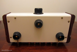
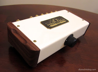
The box could now be assembled and the nicely finished wood panels placed on the sides. Below are a few photos of the finished product.
![]() |
| Switchbox complete! |
![]() |
| Switchbox Front |
![]() |
| Switchbox Rear |
![]() |
| Switchbox Bottom |
Some nice points about this design are the short signal paths thanks to the small chassis, the Teflon insulated wire and RCAs, the gold contacts on the switch and the point to point wiring with no circuit board for the signal to run through. This box could either be used to allow 6 inputs and 1 output, or 1 input and 6 outputs. With a larger box and a second switch, there could be both multiple inputs *and* outputs. Or there could be two of these boxes daisy-chained, allowing for 6 inputs and 6 outputs. Tons of options!
Update: I created a nice little logo "iO" standing for input output and had it custom engraved on a brass plate for the top panel. Looks rather sharp I think :) Some additional photographs with the plate are below.
The Fine Print:The above steps detailing the building of a switch box are for entertainment purposes only and not to be performed under any circumstances. The owner of this blog and all associated parties can not / will not be held responsible if you attempt the process posted and cause physical harm to yourself, your surroundings or your property. Please keep this in mind.